Introduction
In manufacturing and engineering, inspection plays a vital role in confirming whether a component meets specified requirements. Dimensional checks, visual inspection, material testing, welding inspection, and non-destructive testing help organizations identify defects and verify product conformity.
However, a common engineering concern is:
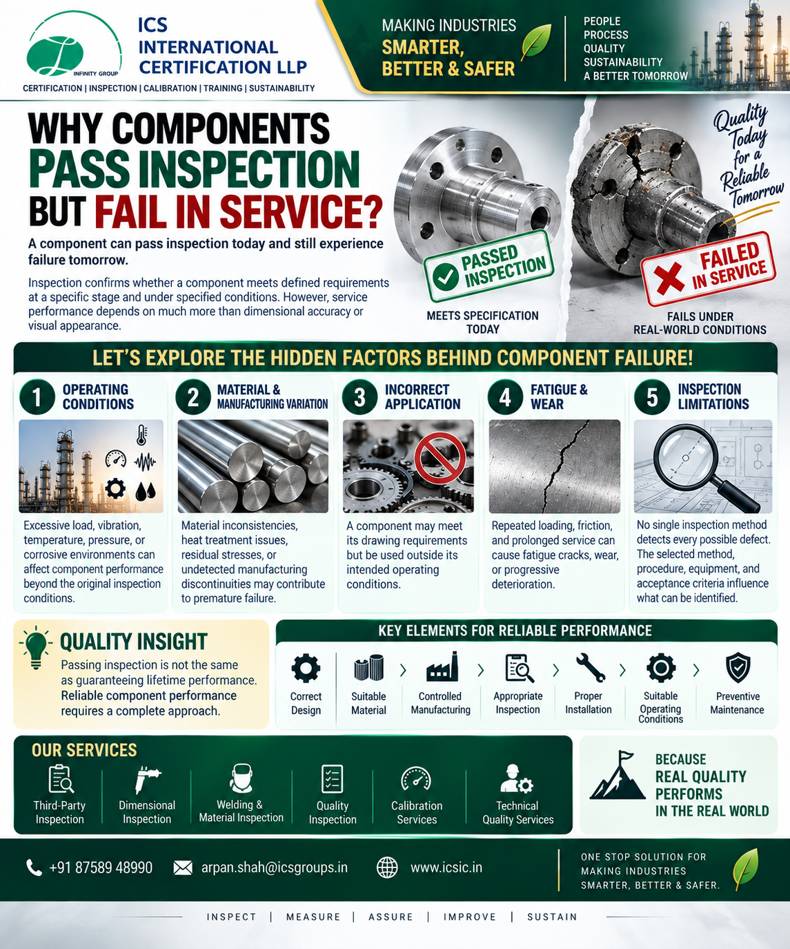
Why does a component pass inspection but fail during service?
A component may meet the applicable inspection requirements at the time of examination and still experience failure during operation. This does not necessarily mean that the inspection was ineffective or that the component was manufactured incorrectly. Inspection is performed under defined conditions, using selected methods, acceptance criteria, and available information.
Actual service performance depends on several additional factors, including operating conditions, material behavior, fatigue, installation, maintenance, and application suitability.
Understanding these factors helps organizations move from simply confirming product conformity to improving long-term reliability, safety, and performance.
1. Passing Inspection Does Not Guarantee Unlimited Service Life
Inspection determines whether a product, component, material, or process meets specified requirements at a particular stage.
For example, an inspection may verify:
- Dimensional accuracy
- Surface condition
- Material identification
- Weld quality
- Geometrical tolerances
- Visible defects
- Applicable acceptance criteria
- Functional or performance requirements, where specified
However, inspection results are based on the scope and conditions of the inspection.
A component that passes inspection has demonstrated conformity with the checked requirements. It does not automatically guarantee that the component will remain defect-free throughout its entire service life under every possible operating condition.
Quality Insight: Inspection confirms conformity against defined requirements. Reliability depends on how the component performs over time and under actual service conditions.
2. Operating Conditions Can Exceed Design Expectations
One of the major reasons for component failure is exposure to operating conditions that are more severe than anticipated.
Components may be subjected to:
- Excessive mechanical loads
- Repeated vibration
- High or low temperatures
- Pressure fluctuations
- Corrosive environments
- Shock loading
- Frequent starting and stopping
- Improper operating conditions
A component may pass dimensional and visual inspection but fail when it experiences loads, temperatures, or environmental conditions beyond its design assumptions.
Example
A shaft may meet its dimensional and surface-finish requirements during inspection. However, if it is exposed to excessive vibration, misalignment, or repeated overloading, cracks may develop during operation.
How to Reduce the Risk
Organizations should verify:
- Whether operating conditions match the design specifications.
- Whether load, temperature, and pressure limits are clearly defined.
- Whether equipment is operated within its intended application.
- Whether abnormal operating conditions are recorded and investigated.
3. Material and Manufacturing Variations
The performance of a component depends significantly on the properties and consistency of its material.
Potential contributing factors include:
- Incorrect material selection
- Material composition variations
- Improper heat treatment
- Inadequate hardness or toughness
- Residual stresses
- Manufacturing discontinuities
- Improper welding parameters
- Inadequate process control
Some material or manufacturing issues may not be detectable through a particular inspection method. The ability to identify a discontinuity depends on factors such as material type, component geometry, defect orientation, inspection procedure, equipment, and acceptance criteria.
Example
A fabricated component may pass visual inspection but later develop a crack due to residual stress, an unsuitable welding procedure, or a discontinuity that was not detectable using the selected inspection method.
Recommended Controls
- Verify material certificates and traceability.
- Use suitable material testing when required.
- Control heat treatment and welding processes.
- Apply appropriate non-destructive testing methods.
- Review manufacturing parameters and process records.
- Investigate recurring material-related failures.
4. Fatigue Failure Due to Repeated Loading
Fatigue is a failure mechanism that can occur when a component experiences repeated or fluctuating stresses over time.
A component may withstand a single load but fail after thousands or millions of loading cycles.
Fatigue-related failure can be influenced by:
- Stress concentration
- Sharp corners or design discontinuities
- Surface defects
- Repeated vibration
- Cyclic loading
- Inadequate design margins
- Corrosion
- Residual stresses
Example
A rotating machine shaft may pass inspection before installation. During service, repeated loading and vibration can initiate a small crack. Over time, the crack may grow until the component fails.
The original inspection may not have detected a crack that had not yet formed or a discontinuity outside the method’s detection capability.
Preventive Measures
- Review fatigue loading during design.
- Reduce unnecessary stress concentrations.
- Control surface quality and manufacturing defects.
- Monitor vibration and operating conditions.
- Schedule inspections based on service risk.
- Use suitable NDT methods when required.
5. Wear, Corrosion, and Environmental Damage
Components can deteriorate during service even when they meet inspection requirements at the time of manufacture or delivery.
Common deterioration mechanisms include:
Wear
Repeated contact, friction, or movement can gradually reduce component dimensions and affect performance.
Corrosion
Exposure to moisture, chemicals, salt, or aggressive environments can weaken materials and reduce their effective thickness.
Erosion
High-velocity fluids or particles can remove material from surfaces.
Thermal Damage
Repeated temperature changes or excessive heat can affect material properties, dimensional stability, or joint integrity.
Example
A component may pass its initial inspection but experience corrosion during service because the actual environment is more aggressive than expected or because protective coatings and maintenance controls are inadequate.
Risk Reduction Measures
- Select materials suitable for the operating environment.
- Apply appropriate protective coatings.
- Monitor corrosion and wear.
- Establish preventive maintenance schedules.
- Inspect critical areas at suitable intervals.
- Record service conditions and deterioration trends.
6. Incorrect Application or Improper Installation
A component may be manufactured correctly and pass inspection but fail because it is installed or used incorrectly.
Possible causes include:
- Incorrect assembly
- Misalignment
- Improper tightening torque
- Incorrect installation orientation
- Inadequate support
- Incorrect component selection
- Improper lubrication
- Use outside the intended application
- Installation damage
Example
A bearing may pass dimensional inspection but fail prematurely due to incorrect alignment, insufficient lubrication, excessive loading, or contamination during installation.
This highlights the importance of considering the complete system rather than evaluating the component in isolation.
Recommended Practices
- Follow approved installation procedures.
- Verify alignment and assembly requirements.
- Use the correct tools and torque values.
- Train installation personnel.
- Check lubrication and cleanliness requirements.
- Perform commissioning checks before operation.
7. Inspection Has Defined Limitations
No single inspection method can detect every possible defect in every component.
The effectiveness of inspection depends on:
- Inspection method
- Equipment capability
- Inspector competency
- Component geometry
- Material properties
- Defect size and orientation
- Surface accessibility
- Inspection procedure
- Acceptance criteria
- Sampling plan
- Environmental conditions
Examples of Inspection Limitations
Visual Inspection (VT): Primarily identifies visible surface conditions and accessible defects. It may not detect internal discontinuities.
Liquid Penetrant Testing (PT): Can identify suitable surface-breaking discontinuities on compatible, non-porous surfaces but does not normally reveal internal defects.
Magnetic Particle Testing (MT): Detects suitable surface and near-surface discontinuities in ferromagnetic materials. Its effectiveness depends on magnetization, defect orientation, and other conditions.
Ultrasonic Testing (UT): Can detect and evaluate suitable internal discontinuities, but results depend on material, geometry, probe selection, calibration, procedure, and operator competency.
Radiographic Testing (RT): Can reveal certain internal variations, but detection depends on factors such as defect orientation, density differences, component geometry, and technique.
Therefore, inspection planning should be based on the expected failure mechanisms and the risks associated with the component.
8. Measurement Errors and Calibration Issues
Inspection decisions rely on the accuracy and suitability of measurement instruments.
An incorrectly calibrated, damaged, unsuitable, or improperly used instrument can produce unreliable results.
Potential contributors include:
- Instrument calibration overdue
- Incorrect instrument selection
- Poor resolution
- Damaged measuring surfaces
- Temperature variation
- Incorrect measurement technique
- Operator-related errors
- Inadequate measurement uncertainty consideration
Example
A component may be accepted based on an inaccurate dimensional measurement. During assembly or operation, the actual deviation may cause misalignment, excessive stress, leakage, or premature wear.
Good Measurement Practices
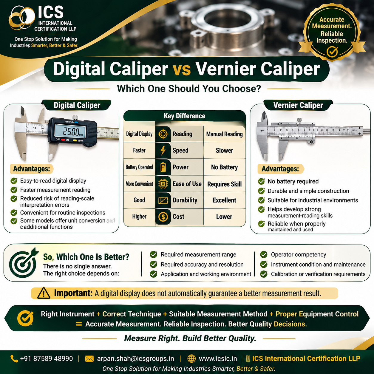
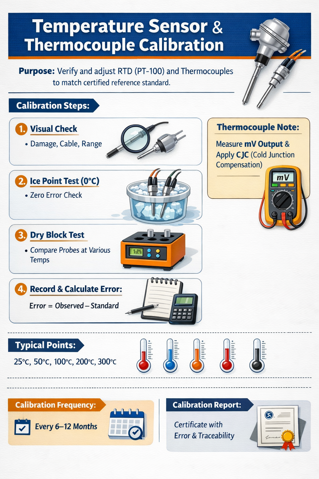
- Use calibrated instruments where required.
- Select instruments appropriate to the tolerance.
- Verify instrument condition before use.
- Consider environmental conditions.
- Train personnel in measurement techniques.
- Maintain calibration and inspection records.
- Review measurement uncertainty for critical applications.
Important: Calibration improves confidence in measurement results, but calibration alone does not guarantee that the instrument, method, operator, and application are suitable for every measurement.
9. Acceptance Criteria May Not Cover Every Service Risk
Inspection acceptance criteria are developed for a defined purpose. A component can comply with those criteria while still having a risk that is not addressed by the inspection scope.
For example:
- A dimensional inspection may not evaluate fatigue life.
- A visual inspection may not identify internal discontinuities.
- A material certificate may not confirm every aspect of the component’s service behavior.
- A surface inspection may not assess system-level misalignment.
- A final inspection may not reproduce actual operating loads.
This is why inspection requirements should be connected to the component’s design function, service conditions, and potential failure modes.
Key Question
Instead of asking only:
“Does the component meet the drawing requirements?”
Organizations should also ask:
“Are the specified requirements sufficient to control the risks associated with the intended service?”
10. The Importance of Root Cause Failure Analysis
When a component fails after passing inspection, repeating the inspection alone may not identify the actual cause.
A structured Root Cause Analysis (RCA) should consider the complete history of the component.
Important Investigation Areas
- Design: Was the component designed for the actual loading and operating conditions?
- Material: Was the correct material used, and was traceability maintained?
- Manufacturing: Were the applicable processes controlled?
- Inspection: Were suitable methods, procedures, and acceptance criteria used?
- Installation: Was the component installed correctly?
- Operation: Was the component used within its specified limits?
- Maintenance: Were inspection and maintenance schedules followed?
- Environment: Did corrosion, temperature, contamination, or other external factors contribute?
- Failure Mode: Did the component fail due to fatigue, fracture, wear, corrosion, overload, or another mechanism?
Useful Evidence
- Failed component photographs
- Fracture surface examination
- Material certificates
- Inspection reports
- Calibration records
- Manufacturing and heat-treatment records
- Welding documentation
- Operating data
- Maintenance history
- Previous failure records
The objective is to identify the underlying cause and prevent recurrence—not simply to assign responsibility.
11. How Organizations Can Reduce Component Failures
Reducing service failures requires a coordinated approach involving design, manufacturing, inspection, installation, and maintenance.
1. Strengthen Design Review
Review expected loads, fatigue risks, environmental conditions, tolerances, and material suitability.
2. Select Appropriate Inspection Methods
Choose inspection methods based on the likely defect types, component material, geometry, accessibility, and service risks.
3. Improve Manufacturing Process Control
Monitor critical manufacturing parameters, welding procedures, heat treatment, machining operations, and traceability.
4. Use Suitable Measurement Equipment
Ensure measuring instruments are appropriate, maintained, and calibrated as required.
5. Verify Installation and Commissioning
Check alignment, tightening, lubrication, assembly, and other installation requirements.
6. Monitor Actual Service Conditions
Track vibration, temperature, pressure, load, wear, corrosion, and other relevant indicators.
7. Implement Risk-Based Maintenance
Determine maintenance and inspection intervals according to component criticality, operating conditions, and failure consequences.
8. Conduct Failure Investigations
Document failures, identify root causes, and implement corrective and preventive actions.
9. Maintain Technical Records
Maintain inspection reports, material certificates, calibration records, manufacturing documents, and service history.
12. Role of Third-Party Inspection in Improving Reliability
Third-party inspection can provide an independent evaluation of specified requirements during manufacturing, procurement, fabrication, installation, or delivery.
Depending on the agreed scope, third-party inspection services may include:
- Material inspection
- Visual inspection
- Dimensional inspection
- Fabrication inspection
- Welding inspection
- Review of manufacturing documentation
- Verification of test reports
- Inspection against drawings and specifications
- Witnessing specified tests
- Inspection reporting and documentation
Third-party inspection does not eliminate all potential service failures. Its value depends on clearly defined inspection scope, competent personnel, suitable procedures, appropriate acceptance criteria, and effective communication of findings.
When inspection planning is aligned with component risks, it can support better quality decisions and reduce the likelihood of undetected nonconformities.
13. Inspection, Quality Control, and Reliability Must Work Together
Inspection is one part of a broader quality and reliability framework.
| Area | Primary Focus |
|---|---|
| Design | Suitability for intended service conditions |
| Manufacturing | Controlled and consistent production |
| Quality Control | Monitoring and controlling product conformity |
| Inspection | Verification against specified requirements |
| Calibration | Confidence in measurement results |
| Installation | Correct assembly and commissioning |
| Maintenance | Maintaining performance during service |
| Failure Analysis | Identifying causes and preventing recurrence |
A reliable component is not created by inspection alone. It is the result of coordinated controls throughout the product life cycle.
Conclusion
A component can pass inspection and still fail in service because inspection is performed within defined limits, while actual service performance is influenced by changing loads, fatigue, wear, corrosion, installation, maintenance, material behavior, and operating conditions.
Passing inspection is an important quality milestone—but it is not a guarantee of unlimited service life.
To improve component reliability, organizations should combine:
- Appropriate design and material selection
- Controlled manufacturing processes
- Risk-based inspection planning
- Suitable testing and measurement methods
- Proper installation
- Monitoring of operating conditions
- Preventive maintenance
- Structured failure analysis
The most effective quality approach looks beyond whether a component passed inspection and considers whether it is suitable, reliable, and safe for its intended application.
How ICS International Certification LLP Can Support Your Quality Requirements
ICS International Certification LLP supports organizations with professional quality, inspection, calibration, training, certification, and compliance-related services designed to strengthen manufacturing controls and operational reliability.
Our service areas include:
- Third-Party Inspection
- Dimensional Inspection
- Material Inspection
- Visual Inspection
- Welding and Fabrication Inspection
- Quality Inspection Services
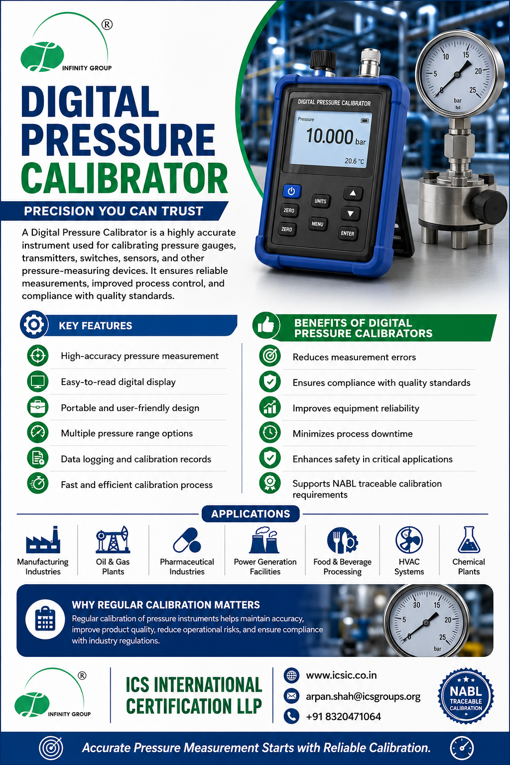
- Calibration Services
- Technical and Quality Training
- Management System Certification Support
- Compliance and Safety Services
One Stop Solution for Making Industries Smarter, Better & Safer.
📞 Contact: +91 87589 48990
📧 Email: arpan.shah@icsgroups.in
🌐 Website: www.icsic.in
Contact ICS International Certification LLP to discuss your inspection, quality, calibration, and compliance requirements.
Frequently Asked Questions (FAQs)
1. Can a component fail even after passing inspection?
Yes. A component may meet the inspected requirements but fail later due to fatigue, overload, corrosion, wear, improper installation, unsuitable operating conditions, or other factors.
2. Does passing inspection guarantee component reliability?
No. Inspection confirms conformity against defined requirements and conditions. Long-term reliability also depends on design, materials, manufacturing, installation, operation, and maintenance.
3. Why is root cause analysis important after component failure?
Root cause analysis helps identify the underlying reasons for failure and supports corrective actions to reduce the risk of recurrence.
4. Can NDT detect every type of defect?
No. Each NDT method has specific capabilities and limitations. Method selection should consider material, geometry, defect type, accessibility, procedure, and acceptance criteria.
5. How does calibration support inspection quality?
Calibration provides evidence of measurement accuracy against established references. However, the instrument must also be suitable for the measurement range, tolerance, environment, and application.
6. How can third-party inspection help reduce component failures?
Third-party inspection can provide independent verification of specified requirements, materials, dimensions, fabrication quality, testing, and documentation, depending on the agreed scope.