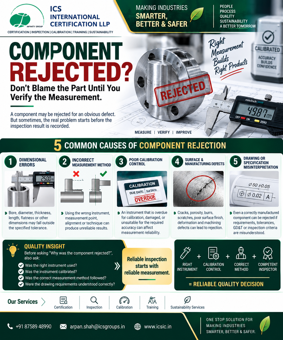
5 Common Causes of Component Rejection and How Calibration Can Help
Component rejection is a common challenge across manufacturing, machining, fabrication, engineering, automotive, and industrial production.
A component may be rejected because of a dimensional error, manufacturing defect, incorrect specification, or an unreliable inspection result. While some rejection causes are directly related to manufacturing, others can originate from the measurement and inspection process itself.
This is why calibration and measurement control are important parts of an effective quality management system.
A simple quality principle is:
You cannot make reliable decisions from unreliable measurements.
In this blog, we explore 5 common causes of component rejection and explain how proper measurement practices and calibration can help reduce avoidable quality problems.
What Is Component Rejection?
Component rejection occurs when a manufactured component does not meet one or more specified requirements.
The requirements may relate to:
- Dimensions
- Tolerances
- Material properties
- Surface finish
- Geometry
- Appearance
- Welding quality
- Functional performance
- Drawing requirements
- Customer specifications
- Applicable standards
A rejected component may require rework, repair, sorting, concession, or scrapping, depending on the nature of the nonconformity and the applicable requirements.
1. Dimensional Errors
One of the most common reasons for component rejection is a dimensional measurement falling outside the specified tolerance.
Typical dimensional characteristics include:
- Length
- Width
- Thickness
- Bore diameter
- Outside diameter
- Hole diameter
- Depth
- Flatness
- Height
- Angle
- Radius
For example, suppose an engineering drawing specifies:
Ø50.00 ± 0.02 mm
The acceptable range is:
49.98 mm to 50.02 mm
If the measured diameter is 50.05 mm, the component does not meet that specified dimensional tolerance.
What Can Cause Dimensional Errors?
Dimensional variation may result from:
- Tool wear
- Incorrect machine settings
- Incorrect machining parameters
- Fixture problems
- Material movement
- Thermal effects
- Operator errors
- Incorrect drawing interpretation
- Manufacturing process variation
How Can Calibration Help?
Calibration does not correct a manufacturing process, but it helps ensure that the measurement equipment being used to evaluate the component is suitable and provides reliable measurement information.
2. Incorrect Measurement Method
Having a calibrated instrument does not automatically guarantee a correct measurement.
The measurement method also matters.
For example, an inspector may use an appropriate micrometer but apply it incorrectly, measure at an unsuitable location, or fail to align the instrument properly.
This can produce an unreliable result.
Common Measurement Method Errors
Examples include:
❌ Incorrect measurement location
❌ Incorrect instrument selection
❌ Poor alignment
❌ Excessive measuring force
❌ Measuring over burrs or contamination
❌ Incorrect zero/reference setting
❌ Measuring a feature in an unsuitable orientation
❌ Recording the wrong value
Example
Consider a cylindrical bore.
A single measurement at one location may appear acceptable, while measurements at different depths or orientations could reveal:
- Taper
- Ovality
- Local variation
Therefore, the inspection method should be defined according to the drawing, inspection plan, component geometry, and required accuracy.
3. Poor Calibration Control
📏 Calibration is a critical part of measurement control.
Manufacturing organizations use numerous instruments to determine whether components meet specified requirements.
Examples include:
- Vernier calipers
- Micrometers
- Bore gauges
- Dial indicators
- Height gauges
- Pressure gauges
- Temperature measuring instruments
- Torque measuring equipment
- CMMs
- Measuring standards
If measurement equipment is not properly controlled, the reliability of inspection results can be affected.
What Is Calibration?
Calibration is the process of establishing the relationship between the values indicated by a measuring instrument and corresponding values provided by measurement standards, under specified conditions.
Calibration can provide information about:
- Instrument error
- Measurement deviation
- Traceability
- Measurement performance
- Suitability for intended use
A calibration certificate may therefore provide important information about the condition and performance of the instrument at the time of calibration.
Calibration Is More Than a Sticker
A common misconception is:
“The instrument has a calibration sticker, so the measurement must be correct.”
Not necessarily.
Effective measurement equipment control should consider:
- Instrument identification
- Calibration status
- Calibration interval
- Calibration records
- Measurement range
- Accuracy requirements
- Instrument condition
- Handling and storage
- Protection from damage
- Suitability for intended measurement
The instrument must also be used correctly.
A calibrated instrument used incorrectly can still produce an unreliable measurement.
4. Surface and Manufacturing Defects
Not every rejection is caused by dimensional problems.
A component may meet its dimensional requirements but still contain a manufacturing defect.
Depending on the component and applicable requirements, examples may include:
- Cracks
- Porosity
- Inclusions
- Burrs
- Scratches
- Corrosion
- Deformation
- Poor surface finish
- Welding discontinuities
- Casting defects
- Forging defects
- Machining marks
Different inspection methods may be required to identify these conditions.
Visual Inspection
Visual inspection can identify many visible surface conditions.
NDT
Depending on material and requirements, NDT methods may include:
- Visual Testing (VT)
- Liquid Penetrant Testing (PT)
- Magnetic Particle Testing (MT)
- Ultrasonic Testing (UT)
- Radiographic Testing (RT)
The appropriate method depends on the material, geometry, expected discontinuity, specification, and acceptance criteria.
Dimensional Inspection
Dimensional inspection verifies whether measurable characteristics conform to drawing requirements.
This demonstrates why no single inspection method can identify every type of nonconformity.
5. Drawing or Specification Misinterpretation
Sometimes a component can be manufactured correctly according to one interpretation but still fail to meet the actual requirement because the drawing or specification was misunderstood.
Engineering drawings may contain:
- Nominal dimensions
- Dimensional tolerances
- GD&T requirements
- Surface finish requirements
- Material specifications
- Heat treatment requirements
- Welding requirements
- Inspection notes
- Special process requirements
An inspector or production team must understand which requirements apply to the component.
Common Interpretation Problems
Examples include:
❌ Misreading dimensional tolerances
❌ Ignoring drawing notes
❌ Incorrect interpretation of GD&T
❌ Confusing reference dimensions with controlling dimensions
❌ Using an incorrect measurement method
❌ Overlooking surface-finish requirements
❌ Measuring the wrong feature
Clear communication between design, production, quality, and inspection teams is therefore essential.
How Calibration Can Help Reduce Avoidable Rejection
Calibration cannot prevent every component defect.
However, effective calibration and measurement control can help reduce measurement-related uncertainty and avoidable incorrect inspection decisions.
Consider this quality chain:
Engineering Drawing
⬇️
Manufacturing
⬇️
Measurement
⬇️
Inspection
⬇️
Acceptance / Rejection Decision
If the measurement stage produces unreliable information, the final decision can also be affected.
For example, an acceptable component could potentially be rejected because of an inaccurate measurement, or a nonconforming component could potentially be accepted if the measurement system does not reliably identify the deviation.
The Importance of Instrument Selection
Calibration alone is not enough.
The instrument must also be appropriate for the measurement.
For example, if a component has a very tight dimensional tolerance, using a general-purpose instrument that does not provide adequate resolution or accuracy may not be appropriate.
Instrument selection should consider:
- Required measurement range
- Required accuracy
- Resolution
- Tolerance of the component
- Feature geometry
- Measurement environment
- Measurement method
- Applicable inspection requirements
Right Instrument + Right Method + Proper Calibration = More Reliable Measurement
Environmental Factors Can Affect Measurement
Precision measurements can also be influenced by environmental conditions.
Important factors may include:
Temperature
Materials and measuring equipment can expand or contract with temperature changes.
Cleanliness
Dirt, chips, oil, burrs, or contamination between the instrument and component can affect readings.
Alignment
Incorrect alignment can introduce measurement errors.
Measuring Force
Excessive force may affect some measurements, particularly when measuring flexible or delicate components.
Vibration
Certain precision measuring systems can be affected by vibration or unstable environments.
Therefore, measurement procedures should address environmental and handling conditions where they are significant.
What Happens When an Instrument Is Found Out of Calibration?
If an instrument is found to be outside its specified calibration requirements, the organization should determine what action is necessary according to its documented procedure and applicable requirements.
Depending on the situation, this may involve:
- Identifying the affected instrument.
- Reviewing its calibration history.
- Determining the period potentially affected.
- Identifying measurements or products that may have been evaluated using the instrument.
- Assessing the significance of the measurement error.
- Taking appropriate corrective action.
- Documenting the evaluation and results.
This is important because an out-of-calibration instrument does not automatically mean that every previous measurement is invalid.
The impact needs to be evaluated based on the actual circumstances and measurement requirements.
Calibration and ISO 9001
Measurement equipment control is an important element of quality management.
Organizations implementing ISO 9001 should determine and provide appropriate monitoring and measuring resources when they are needed to verify conformity of products and services.
Where measurement traceability is required, appropriate controls over measuring equipment, calibration or verification, identification, and protection are important.
The exact controls should be established based on the organization’s processes, risks, applicable requirements, and intended measurement use.
A Simple Example of Measurement-Related Rejection
Imagine a machined shaft with a specified diameter:
Ø25.00 ± 0.01 mm
The actual acceptable range is:
24.99 mm to 25.01 mm
An inspector measures the shaft using a measuring instrument that has not been properly controlled.
The displayed reading is:
25.02 mm
The component is rejected.
But what if the measurement system itself has an error that materially affects the result?
The organization now has to determine whether the rejection decision was justified.
This example illustrates why measurement equipment control and calibration are important to quality decisions.
5 Questions to Ask Before Rejecting a Component
Before finalizing a dimensional rejection, quality teams can consider:
1. Was the correct drawing revision used?
An outdated drawing can lead to incorrect acceptance criteria.
2. Was the correct measuring instrument selected?
The instrument must be suitable for the required measurement.
3. Is the instrument within its required calibration status?
Calibration status should be verified.
4. Was the correct measurement method followed?
Location, alignment, force, environment, and procedure may matter.
5. Is the result clearly documented?
Actual measurement results and relevant inspection information provide useful traceability.
How to Reduce Component Rejection
Organizations can strengthen quality control through a systematic approach.
Step 1: Understand Requirements
Review drawings, specifications, tolerances, and inspection requirements.
Step 2: Control Manufacturing
Monitor processes that influence critical dimensions and characteristics.
Step 3: Select Suitable Instruments
Use measuring equipment appropriate to the required accuracy.
Step 4: Maintain Calibration Control
Ensure measuring equipment is appropriately calibrated or verified according to established requirements.
Step 5: Standardize Measurement Methods
Use documented procedures where necessary.
Step 6: Train Personnel
Ensure inspectors and operators understand the measurement process.
Step 7: Record Actual Results
Maintain inspection and measurement records for traceability.
Step 8: Investigate Rejections
When a component is rejected, determine whether the cause is:
Manufacturing → Measurement → Method → Material → Specification → Documentation
This approach can help identify the true root cause rather than simply correcting the rejected component.
Final Takeaway
Component rejection is not always simply a manufacturing problem.
It can result from a combination of:
Dimensional variation + Manufacturing defects + Measurement method + Instrument condition + Calibration control + Specification interpretation.
Calibration plays an important role in ensuring that measuring equipment remains controlled and suitable for its intended use.
But remember:
Calibration alone does not guarantee measurement accuracy.
Reliable inspection requires the complete chain:
Right Specification
↓
Right Instrument
↓
Proper Calibration
↓
Correct Measurement Method
↓
Competent Personnel
↓
Reliable Inspection Result
At ICS International Certification LLP, we support industries with Calibration, Dimensional Inspection, Third-Party Inspection, Quality Inspection, and Technical Quality Services, helping organizations strengthen measurement and quality control processes.
📞 +91 87589 48990
📧 arpan.shah@icsgroups.in
🌐 www.icsic.in
ICS International Certification LLP
One Stop Solution for Making Industries Smarter, Better & Safer.